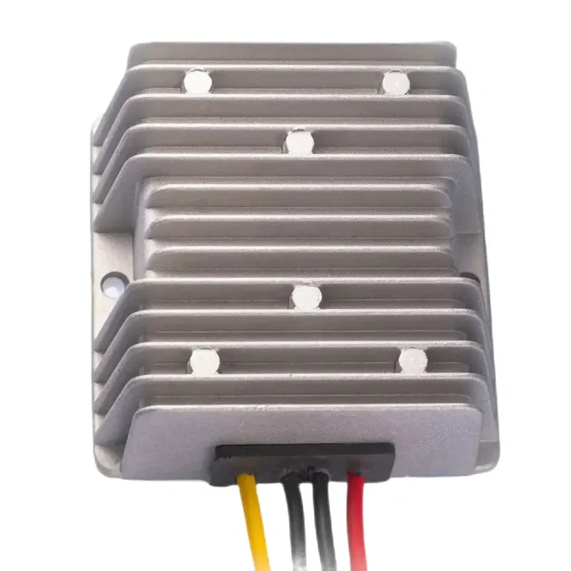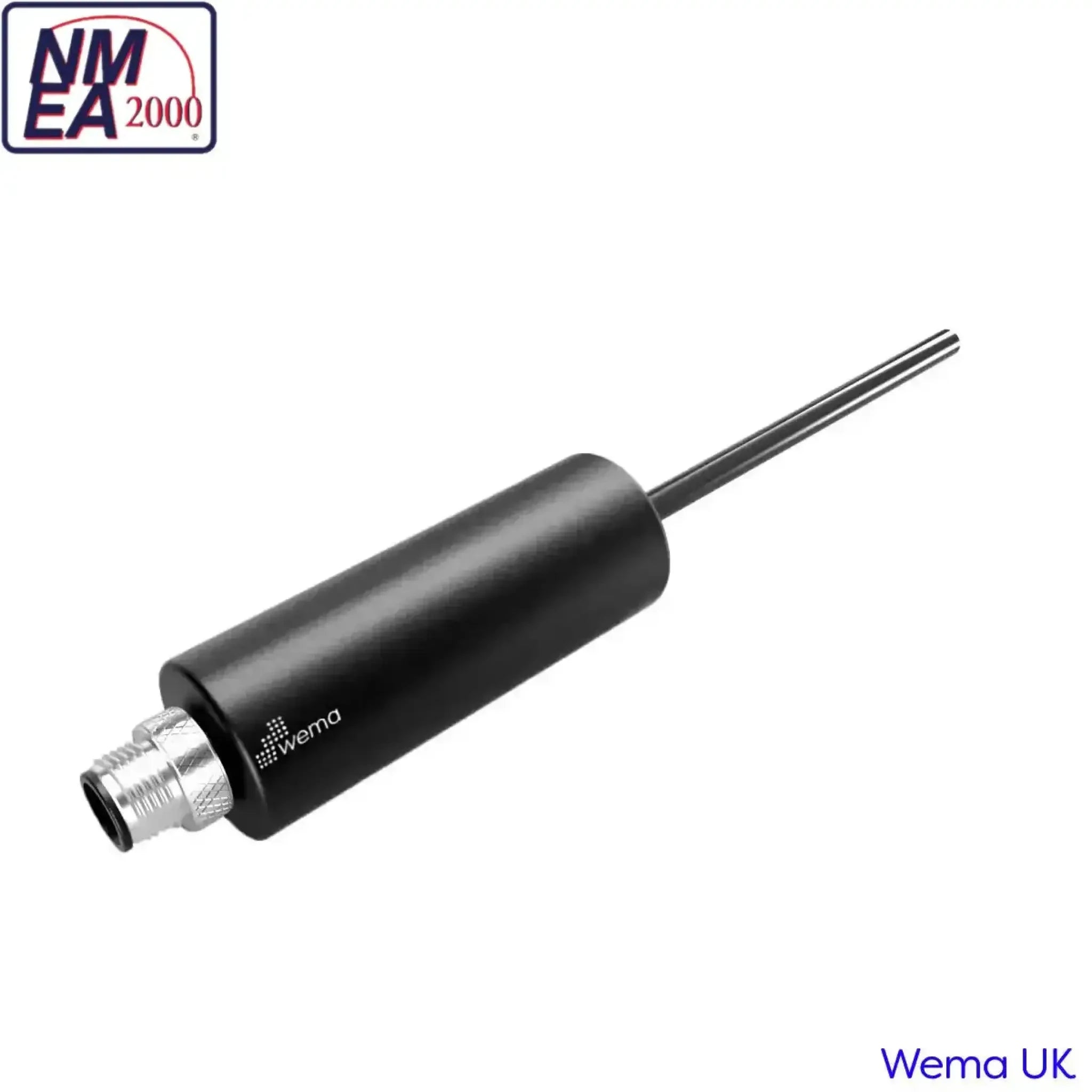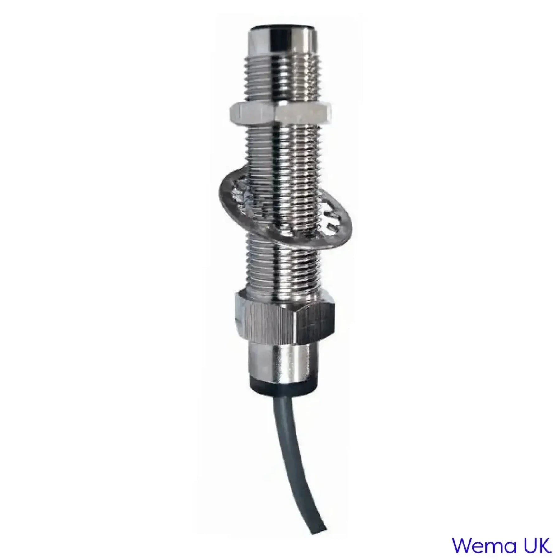

The Inductive Sensor works with the Tachometer as alternative to taking a feed from the W terminal on the alternator.
The inductive sensor counts the gear rotation speed. It's main advantages include a stable output signal; wide range of operational temperatures, small size and simple assembly process.
It covers a wide range of measurements including zero rotation speed.
This sensor applies induction to measure the speed of the flywheel; it has large output signal, good anti-interference, no need of amplification or external power supply.
It can be used in severe circumstances such as smog, oil, moisture, etc.
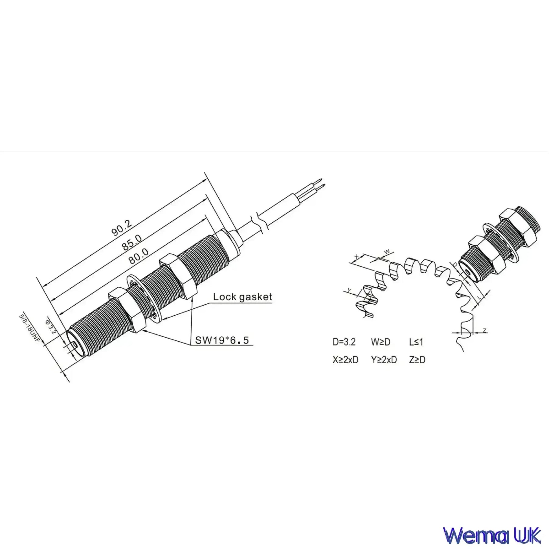
Sensor can be assembled at the radial position of the gear; distance between the sensor end and the gear top (air gap) is about 1mm, the smaller the distance is, the bigger output signal will be. To get a large output signal and sinusoidal waveform, the involute gear must have more than 2 gear modules, and distance between the sensor end and the gear top no less than 1mm. Output voltage waveform: involute gear is approximate to sinusoidal wave.
The choice of shipping options is calculated at the checkout.
The price and available shipping options will depend on your location as well as the size and weight of your order.
If you choose 'free delivery' or some Royal Mail services, the order may not be trackable for the duration of the journey and only show tracking events when the order is shipped and when it is delivered.
We aim to dispatch all morning (GMT) orders the same day and all orders received afternoon or at weekends the following business day.
Once your order has shipped you will be notified by email.
What resistance is it?
How long is it?
How many wires does it have?
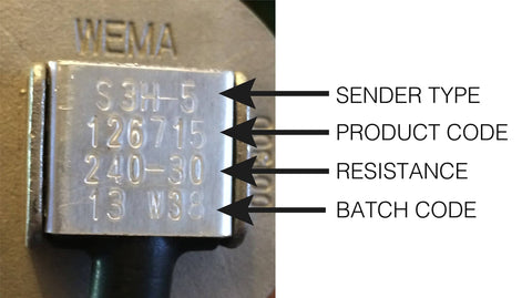
If your sender has information stamped on the head then we can identify your sender from the product code:
[Please note: the code 001300 refers to the S3 head and the code 001306 / 001305 refers to the S5 sender head]
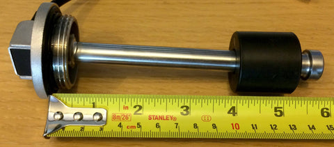
The S3 sender has a screw in head with a 1.25" BSP thread like this:
[NOTE: A 1.25" BSP (British Standard Pipe) thread will actually measure larger than 1.25 inches when measured with a tape measure. This is because a BSP measurement refers to the internal bore of a pipe (for accurate flow rate) and not the outside of the thread.]

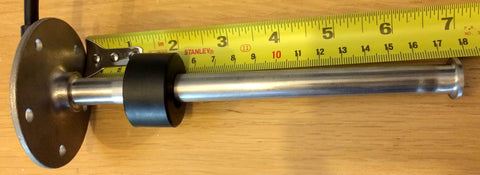
The S5 sender has a bolt down head with 5 holes like this:

[NOTE: The 5-hole drill pattern in the top of an S5 sender head is a standard SAE-5-hole pattern.]
If you have a sender that is not an S3 or S5 then please click here
The sender and gauge must have the same resistance values or the gauge will read incorrectly.
You can either test the gauge or the sender to find this out.
To test the sender:Disconnect the two wires on top of the sender.
Remove the sender from the tank.
Connect the wires on the sender to a multimeter.
Set the multimeter to resistance [Ω ohms]

Move the float to the top of the sender and take a reading on the multimeter:
At the top of the sender (full) the resistance should be:
European specification - 190 ohms
American specification - 30 ohms
Move the float to the bottom of the sender and take a second reading:
At the bottom of the sender (empty) the resistance should be:
European specification - 0 ohms
American specification - 240 ohms
If you have access to the wires on the back of the gauge;
Power the gauge off
Disconnect the black wire (sender)
Power the gauge on
If it's an American gauge the needle will show EMPTY
Touch the black wire to earth, the needle will go to FULL
If it's a European gauge the needle will show FULL
Touch the black wire to earth, the needle will go to EMPTY
If you don't have access to the back of the gauge;
Disconnect the two wires in the loom that attach to the sender.
If it's an American gauge the needle will show EMPTY
If it's a European gauge the needle will show FULL
To measure an S3 or S3H sender (with screw in head) measure from the top of the thread to the bottom of the stem.
To measure an S5 sender (with bolt down head) measure from the underside of the flange to the bottom of the stem
If your S5 or S3 sender has 2 wires then it is a standard resistance sender.
If your S5 or S3 sender has 3 or 4 wires then it is either a 0-5v, 0-10v sender or it has a high/low level alarm.
If you have a 3 or 4 wire sender then please contact us before ordering.
If your sender has a high or low level alarm we will need to know if the switch is normally off (when the tank is empty), turning on when the tank is full or normally on, turning off when the tank is full. We will also need to know how far from the top or bottom of the sender you would like the alarm switch to be.
For fuel or water then you can fit the maximum length of sender for your tank.
For a black water holding tank we recommend leaving at least 50mm from the bottom of the tank regardless of the material the tank is made from.
If you tank does not contain fuel, fresh water, grey water or black water then please contact us for more specific information. For very thick liquids like oil or grease we may need to know the viscosity.
Wema Sender Identification Chart
(click here for larger view)