
Wema Tachometer FAQs
Tachometer Frequently Asked Questions
Wema tachometers need to be calibrated before use. They should only be installed by a qualified marine electrician. These FAQs are for their reference.
Our tachometers are designed to work with either a feed from the W terminal on the alternator or from an Inductive Sensor.
All of Wema tachometers have an incorporated hourmeter.
Our multi-function tachometers also have other functions built in.
The tachometer can process both sine and square signals.
If connecting to the alternator, simply connect the black wire from the tachometer to the W terminal on the alternator.
If connecting to an Inductive Sensor, please consult a qualified professional.
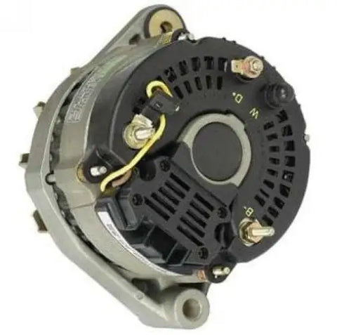
Please note: The analogue 3k tachometer (pictured) is special order only (available with MOQ of 25). Two versions are stock items; the 4k & 8k. Any of the other tachometers pictured above will work for a 3k setup. Please contact us for further information.
INSTALLATION STEPS:
1. Cut a 85 mm(3 3/8") diameter panel hole(II). You will need a minimum clearance of 55mm(2 3/16") behind the panel to fit the gauge.
2. Take off the fastening ring(I),place the gauge into the panel hole, adjust its position and then fasten the rear cover.
3. According to the wiring diagram, the gauge can be connected to 12VDC or 24VDC power.
4. Select either red or yellow wire to give backlight colour.
5. Insert the wiring loom connector into the gauge (IV), adjust its speed ratio to get a suitable reading on the gauge. 6. Calibrate tachometer as per instructions below.
INSTALLATION NOTES:
1) Wema tachometers must be calibrated to the engine before use. They are not for DIY installation. These instructions are for use by a qualified marine electrician who has access to the correct equipment.
2) Customer installation is possible if engine specifications are known.
3) If specifications are unknown then it is often possible to connect the tachometer to the W-terminal on the alternator and cycle through settings until the known idling RPM is displayed on the gauge. The throttle can then be depressed to check that the full range of movement is displayed on the gauge.
PROFESSIONAL INSTALLATION GUIDELINES:
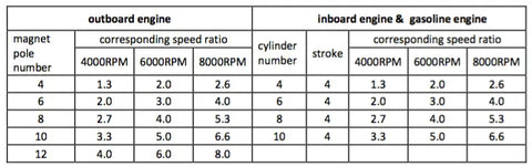
Q – The number of the magnet poles (outboard engine), or number of the cylinders (inboard engine);
Max – The maximum speed the gauge can read;
R – The speed ratio to be set;
FORMULA:
R = (Q/2 )* (Max/6000)
For example: For a 3 cylinder, 4 stroke engine where the full scale of the tachometer is 4000RMP;
R=(3/2)*(4000/6000)=1.0;
Adjust the speed ratio on the tachometer to 1.0.
If it is a two stroke engine, speed ratio = 3*(RPM/6000);
For example, if it is a 4000RPM Tacho, speed ratio = 3*(4000/6000)=2;
Based on the calculated results, enter the settings mode and adjust it to the corresponding speed ratio.
SPEED RATIO ADJUSTMENT:
a. Hold down the rubber button on the back of the gauge for 3 seconds; it will then enter 'settings mode'.
If the button is held for more than 3 seconds, it will exit settings mode.
b. As the button is pressed, the value will increase.
To decrease the value; release the button and press again. The value will now decrease. The longer you press the button, the faster the value will change.
[The minimum step value is 0.5 and the adjustable range is 0.5 - 250]
c. When you get to the required speed ratio value release the button.
The tachometer will save the selection after 3 seconds.
To re-adjust the value, repeat steps a-c.
[If the deviation is big, the speed ratio can be a bit bigger than calculated value;
If the deviation is small, the speed ratio can be a bit smaller than calculated value.
The gauge needle points at the corresponding positions when adjusting the speed ratio.]
If above calculation description is not clear to you, you can adjust it according to the idle speed of the engine.
The engine remains at idle state after it is started; enter the settings mode and adjust the speed ratio until the gauge needle is close to the idle state.
NOTES:
1. The gauge should be connected to the power source before setting speed ratio.
2. In some locations, where there is heavy tachometer signal disturbance, the needle on the tachometer may not move accurately with the changing of the rotation speed.
If this is the case, please add a resistor between 1/4~1W, 1~20K in series connection to strengthen the signal processing capability. We suggest adding a 20K potentiometer in series connection to test.